Finally we got Stage 2 to work!!! But it was not easy.
We made a simple test program to just cycle colors of the PWR_LED. But that did not work at all, just a blink on the led. #sad_face
    org $FE00

    _START:
    clrb
LOOP:
    stb PWR_LED
    ldx #$03E8
    jsr DELAY_MS
    cmpb #$07
    beq _START
    inca
    bra LOOP

DELAY_MS:
    ; Delay routine...
 ...

STACK EQU $E000

    org $FF00
HOOK_RESTART:
    ; Initialize native mode on the 6309 CPU
    ldmd #$01

    ; Set up the stack
    lds #STACK

    lbra _START

HANG:
    bra HANG

    org $FFFE

vrestart: fdb HOOK_RESTART
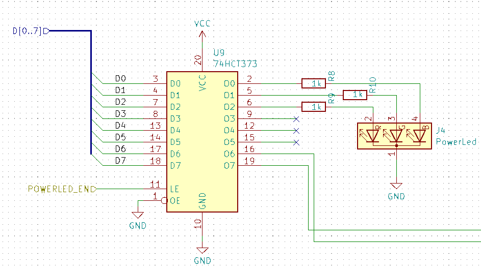
First we found that we missed that the logic of the PWR_LED register was positive, eg. it needed a HIGH enable signal to clock the data in.

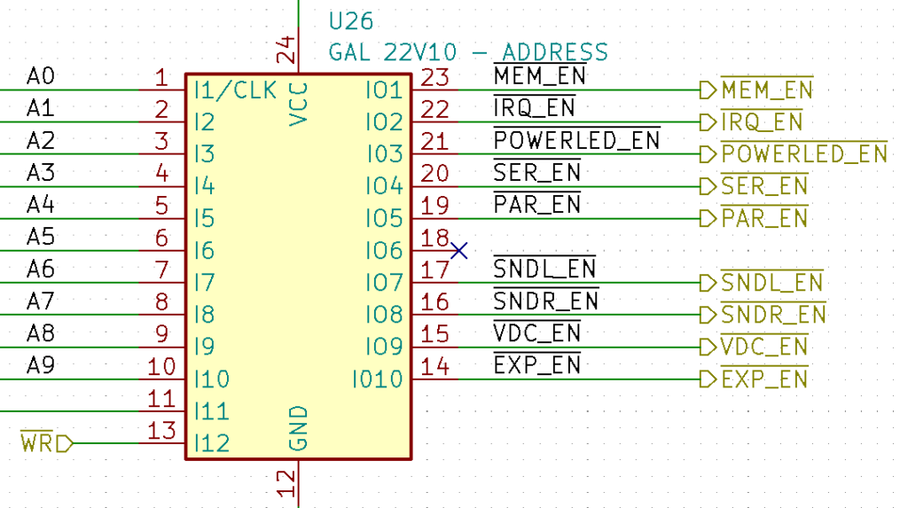
But our address logic was done to create negative enable signals:

So the fix for this was easy, just update the logic code to not invert the enable signal on pin 21, the PWR_LED enable pin.
PIN 14		= !EXP_EN; 		/* Enable Expansion Port           */
PIN 15   	= !VDC_EN; 		/* Enable Video Port               */
PIN 16    	= !SNDR_EN; 		/* Enable Sound Port Right         */
PIN 17    	= !SNDL_EN; 		/* Enable Sound Port Left          */
PIN 18		= !CF_EN; 		/* Enable Compact Flash            */
PIN 19    	= !PAR_EN; 		/* Enable Parallel Port            */
PIN 20    	= !SER_EN; 		/* Enable Serial Port              */
PIN 21    	= PWR_EN; 		/* Enable PowerLed Port            */
PIN 22    	= !IRQ_EN;		/* Enable IRQ Handler              */
PIN 23   	= !MEM_EN; 		/* Enable MMU                      */
After this we still only got a flash of the led and then it turned off. So we tried to just set the register to 0x07, all led pins high. And it did actually set the led to white (or rather blueish, need to adjust the resistors to balance the intensity)
So finally we found that the program was missing some usefull parts. When we tested with branch instructions insted of jumps we got it to work better. That meant that we had not initialized the stack and memory correct. We needed to add initialization of the bank registers, so the address for the stack would be correct and we needed to fix a inca that should be an incb. After these fixes we got the computer to run!!!
Corrected and working code to cycle the PWR_LED:
    org $FE00

PWR_LED EQU $F405
BANK_REG_0 EQU $F400
BANK_REG_1 EQU $F401
BANK_REG_2 EQU $F402
BANK_REG_3 EQU $F403

_START:
    clrb
LOOP:
    stb PWR_LED
    ldx #$03E8
    jsr DELAY_MS
    cmpb #$07
    beq _START
    incb
    bra LOOP

; -----------------------------------------------------------------
; DELAY_MS
; input:            X = Number of milliseconds to delay
; output:           None
; clobbers:         A, X
; There are 2000 cycles per millisecond
; The DELAY_MS function will delay for 11 extra cycles
; -----------------------------------------------------------------
DELAY_MS:
    lda #$7C            ; 2 cycles
DELAY_MS_LOOP:
    nop                 ; 1 cycle
    nop                 ; 1 cycle
    nop                 ; 1 cycle
    deca                ; 1 cycles
    cmpa #$00           ; 4 cycles
    bne DELAY_MS_LOOP   ; 3 cycles
    nop                 ; 1 cycle
    nop                 ; 1 cycle
    nop                 ; 1 cycle
    nop                 ; 1 cycle
    nop                 ; 1 cycle
    nop                 ; 1 cycle
    leax ,-x            ; 5 cycles
    cmpx #$0000         ; 4 cycles
    bne DELAY_MS        ; 3 cycles
    rts                 ; 4 cycles


STACK EQU $1000

    org $FF00
hook_trap:
hook_swi3:
hook_swi2:
hook_swi:
hook_firq:
hook_irq:
hook_nmi:
hook_restart:
    ; Initialize the CPU
    ldmd #$01

    ; Initialize the bank registers
    clra
    sta BANK_REG_0
    sta BANK_REG_1
    sta BANK_REG_2
    sta BANK_REG_3

    ; Set up the stack
    lds #STACK

    lbra _START

hang:
    bra hang


    org $FFF0

vtrap: fdb hook_trap
vswi3: fdb hook_swi3
vswi2: fdb hook_swi2
vfirq: fdb hook_firq
virq: fdb hook_irq
vswi: fdb hook_swi
vnmi: fdb hook_nmi
vrestart: fdb hook_restart
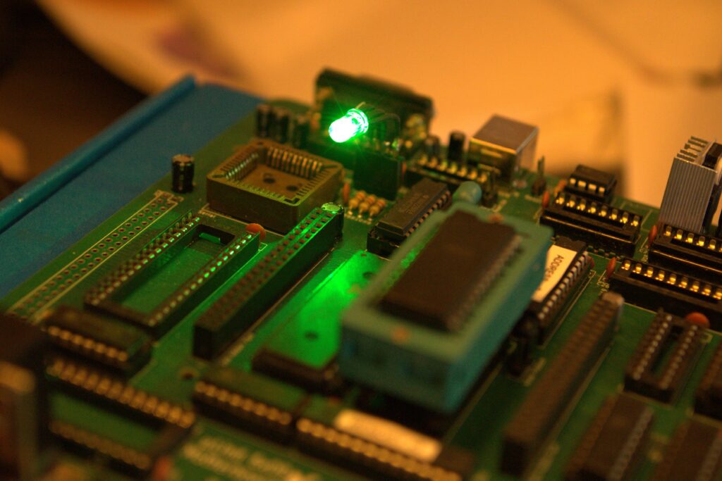
Image of the final working board!

So next step is to add serial controller and the USB interface chip. The drivers for that are already written by my son and he is anxious to try it out!
To infinity and beyond!

