That’s why we prototype it!
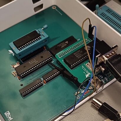
Since we got the base board up and running we wanted to start testing the prototypes so we can order the stage 2 board, with all the fixes and updates. We assembled the parallel port prototype board and plugged it into the base board. Soldered prototype wires for R/W and PAR_EN signals (we forgot to place those on the prototype header) and reprogrammed the logic chip to handle the additional enable signal. But when we wrote a test program nothing happened! The entire board stopped working. Back to the schematics and look thru it closely. EUREKA! Finally we found it!
I had switched the 2 Chip Select ports on the 6522. On is active low and one is active high, and of course had I mixed them up when I made the proto board. Fortunately is it an easy fix, just invert the logic on the logic chip to be active high, so with that we finally got some life in the proto board.

But when we finally made it work one of the ports had a switched pin, so on port A the fire button was connected to the Left pin and vice versa.
So now I have updated the stage 2 and stage 3 schematics with these 2 fixes. And that’s why I made the prototype board before ordering stage 2.
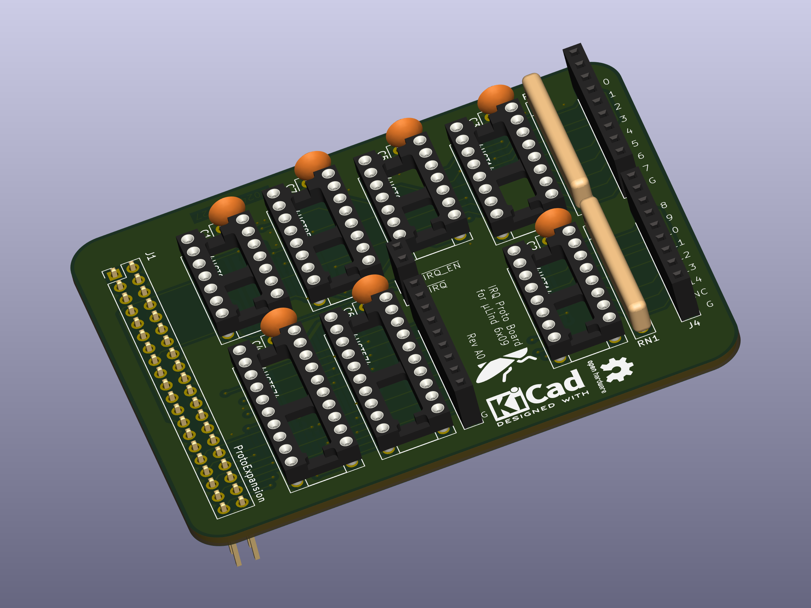
Next up is to assemble the IRQ handler prototype and test that out before I can order stage 2.


