Today we finally got around to set up a test bench for the logic chip. Not fancy and not particularly elaborat, but just enough to get us going forward.
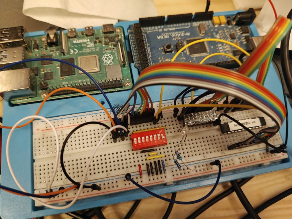
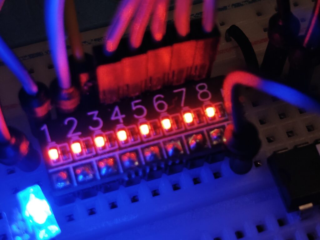
This setup was what we needed to verify the logic CUPL code. And I’m really pleased with the neat led-board i made:
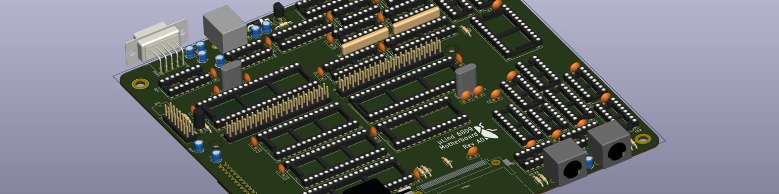
The updated code will generate the following memory map (For Stage2 & Stage3):
| IO Unit | Address | Register |
|---|---|---|
| Memory Mapper | $F400 | MemBlock0 |
| $F401 | MemBlock1 | |
| $F402 | MemBlock2 | |
| $F403 | MemBlock3 | |
| IRQ Handler | $F404 | IRQRead/IRQMask |
| Power LED | $F405 | PowerLedStatus |
| PS2 | $F406 | Keyboard |
| $F407 | Mouse | |
| CF | $F410 | DataRegister |
| $F411 | ErrorReg/FeatureReg | |
| $F412 | SectorCountReg | |
| $F413 | SectorNumberReg | |
| $F414 | CylinderLowReg | |
| $F415 | CylinderHighReg | |
| $F416 | DriveHeadReg | |
| $F417 | StatusReg/CommandReg | |
| $F418 | Unused | |
| $F419 | Unused | |
| $F41A | Unused | |
| $F41B | Unused | |
| $F41C | Unused | |
| $F41D | Unused | |
| $F41E | AltStatusReg/DeviceControlReg | |
| $F41F | DriveAddressReg | |
| Parallel (VIA) | $F420 | InputRegB/OutputRegB |
| $F421 | InputRegA/OutputRegA | |
| $F422 | DataDirectionRegB | |
| $F423 | DataDirectionRegA | |
| $F424 | T1CounterLow / T1LatchLow | |
| $F425 | T1CounterHigh | |
| $F426 | T1LatchLow | |
| $F427 | T1LatchHigh | |
| $F428 | T2CounterLow/T2LatchLow | |
| $F429 | T2CounterHigh | |
| $F42A | ShiftReg | |
| $F42B | AuxControlReg | |
| $F42C | PeripheralControlReg | |
| $F42D | InterruptFlagReg | |
| $F42E | InterruptEnableReg | |
| $F42F | InputRegA/OutputRegA | |
| Serial (XR88C92) | $F430 | ModeRegA |
| $F431 | StatusRegA/ClockSelectRegA | |
| $F432 | CommandRegA | |
| $F433 | RXBufferA/TXBufferA | |
| $F434 | InputPortChangeReg/AuxControlReg | |
| $F435 | InterruptStatusReg/InterruptMaskReg | |
| $F436 | CountTimerUpperReg/CountPreloadUpperReg | |
| $F437 | CountTimerLowerReg/CountPreloadLowerReg | |
| $F438 | ModeRegB | |
| $F439 | StatusRegB/ClockSelectRegB | |
| $F439 | CommandRegB | |
| $F439 | RXBufferB/TXBufferB | |
| $F439 | GeneralPurposeReg | |
| $F439 | InputPortReg/OutputPortControlReg | |
| $F439 | StartCTCommand/SetOutputPortReg | |
| $F439 | StopCTCommand/ResetOutputPortReg | |
| Graphics | $F440 – $F47F | |
| Audio L | $F480 – $F4BF | |
| Audio R | $F4C0 – $F4FF | |
| Expansion Port | $F500 – $F7FF |
So now we need to put all this together on the stage 2 board and start testing that!
Forward and onwards!!!